1. Pre-repair inspection 1.1 The regulator's magnetic field circuit is generally checked with a multimeter (preferably type 500). Check the contacts before cleaning and check the resistance value of each pair of contacts with a multimeter R1 file. Normally, it should be 0. Then follow the steps below to check (in the case of a regulator with 4 additional resistors). (1) The resistance of the two meter pens should be 1Ω when they are connected to the “armature†and “magnetic field†terminals of the regulator, respectively; if the resistance is too large, the 1Ω resistor burns open. (2) Open the contact of the voltage regulator, the resistance value should be about 94Ω; if it is 1Ω, it means that the fixed contact arm of the regulator is short circuited with the iron core frame; if it is about 162Ω, it means that the 13Ω resistance burns open circuit; if it is infinite , indicating 80Ω resistor burns open circuit. (3) Open the current limiter contact and close the voltage limiter contact. The resistance value should be 23Ω; if it is 94Ω, the 30Ω resistance will be burned. 1.2 Check of the regulator's parallel coils Turn the multimeter to the R1 position. The two pens are connected to the “armature†and the adjuster base respectively. At this time, the circuit leading to the voltage divider and the shunt parallel coil is turned on. If the two coils are in good condition, Its resistance value should be 21Ω. If the measured resistance value is about 65Ω, it means that the shunt coil is open circuited; if it is 31Ω, it means that the shunt coil is open circuited; if the resistance value is very small, it means that the coil is short circuited. The short circuit of the series coil, the open circuit and the burn-out of the parallel coil can all be directly observed. Generally, no test is required. 2. Repair of the regulator 2.1 Repair of the contactor In the three pairs of contacts, the voltage regulator is mostly a tungsten contact, and the current limiter and the interceptor are mostly silver-copper contacts. Tungsten contacts are mostly welded and silver and copper contacts are riveted. When the contact is not severely burned, if the thickness is above 0.6mm, it can be repaired with white sand bar or rubbed with oilstone; when the burning is serious, if the pit or thickness is less than 0.4mm, the contact should be replaced. When replacing the current limiter or the closure contact, first use a thin strip to remove the riveted back of the old contact, then use a 2 mm boring head to pull out the old contact, and then use the special contact riveting tool to touch the new contact. Point riveting. If there is no special pressure riveting tool, the contacts can be placed on cardboard or hardwood boards and carefully riveted with a small hammer. When replacing the voltage con- troller contacts, gas welding or battery welding can be used. The latter first clamps the old contacts between the electrodes of the welding device, turns on the power, heats the contacts to melt the solder, and then removes the old contacts; then trims and cleans the soldering surfaces of the contacts with a trowel, and places the thin copper sheets. (Solder) and the new contact are sandwiched between the welding electrodes, the power supply is turned on, and the borax is sprinkled on the contact point, and welding is performed after 3 to 5 seconds. After soldering, the contacts are cleaned in dilute hydrochloric acid and smoothed. After the repair, the contact pair shall have a clean and smooth surface, two contacts adhered tightly, the joint area should be more than 70%, the center offset of the two contacts should not exceed 0.15-0.20mm, and the contact height should not be less than 0.6- 0.7mm. 2.2 Repair of resistors 1Ω resistors are most likely to burn out. They are generally made into individual components and can be replaced with new ones directly after burning. However, some 1 Ω resistors of the regulator are wound on the iron core of the current limiter. When they are replaced, they can be installed between the regulators and the two fixing nuts of the restrictor core. When parts are missing, a constantan wire with a diameter of 0.2mm and a length of 65mm can be used on the mica sheet instead. After the 13Ω, 30Ω, and 80Ω resistors are damaged, they can be replaced directly. 2.3 Repair of the coil If only the external coils of the regulator are open circuited by mechanical damage, the coils can be removed and used repeatedly without rewinding. If the coil insulation is damaged, the internal short-circuit or open circuit must be re-wound. When replacing the coil, the core must be pressed out of the frame, and then the core should be wrapped with a thin insulating paper. Then, according to the specified conductor number, wire diameter, number of turns, winding direction and joint position, system. When winding the series coil on a parallel coil, use a thick insulating paper to protect the parallel coil. The parallel coil of the choke is wound by two pieces of wire with different materials, one part is the enameled wire wound around the outer layer, the number of turns is more, and the other part is the copper wire wound in the inner ring (white, hard, like fine steel wire, large resistance However, it changes with temperature.) If you can't get the copper wire that meets the specifications, you can burn the red wire several times in the old line to make an oxide film on the surface and continue to use it. After the series coil insulation of the current limiter and the interceptor is burned out, the series coil on the old regulator is generally used for repair. 3. First-aid emergency of regulator failure refers to a temporary measure taken by the locomotive when it is in motion, because parts can't be repaired on the spot and no new parts can be replaced. The following describes the six types of first aid methods: (1) After inspection, it was found that the regulator's failure was caused by damage to the interceptor. At this point, the conductor on the battery terminal of the regulator can be removed, and then another lead wire can be connected and then introduced into the cab; another wire can be connected to the intermediate terminal between the flow restrictor and the current limiter. The other end is also introduced into the cab. When the engine is approaching the middle speed, the two wire ends that are introduced into the cab are connected. When the rotation speed is reduced, the two wires are disassembled, and the operation of the interceptor is manually controlled. (2) Upon inspection, the 1 Ω resistor of the regulator is burned out. In this case, a copper wire having a diameter of 0.2 mm and a length of 65 mm may be used instead. If there is no such condition, a thin wire can also be used instead. Then, it is installed between the two core fixing screws of the shutoff and the restrictor. (3) After inspection, it was found that the regulator and the current limiter were damaged. At this time, the conductor on the magnetic field terminal of the generator can be removed, and a 13Ω is connected between the magnetic field terminal of the generator and the armature terminal. Resistance (can be used to remove the acceleration resistor). This is because both the excitation circuit and the excitation current are switched on and the charging current is prevented from being excessively large. It is also possible to connect a light bulb with a resistance of approximately 13Ω in series between the magnetic field of the generator and the armature terminal for temporary first aid. (4) After inspection, the magnetizing coil of the voltage limiter is burned out. At this time, the following methods can be used for emergency: a. Remove the wire on the “Magnetic Field†terminal of the regulator and modify it to the additional resistance (80Ω). And between the acceleration resistor (1 3Ω). b. Remove the wires from the “Armature†and “Magnetic†terminals from the regulator, and then attach a small light bulb between them. (5) After the engine is shut off, the switches of all electrical equipment have been turned off. At this time, the ammeter hands still indicate a large discharge current. The above phenomenon indicates that the contacts of the interceptor are not disconnected. At this time, the engine should be restarted immediately. The generator charges the battery and cuts off the charging circuit by using the wire on the “battery†terminal removed from the regulator, and then carefully inspects it to find out why the contact of the interceptor cannot be disconnected and remove it. (6) If the regulator is severely damaged, or if it is not possible to determine the location of the fault at a time, the pressure regulator, current limiter, and closure emergency aid method may be used in combination. The difference is that the regulator battery terminal and the armature terminal conductor must be removed at the same time, and then a piece of wire should be connected to the cab. In summary, it should be noted that the above-mentioned first-aid method is only applicable to the temporary emergency of the locomotive in the middle of driving. After the locomotive arrives at the destination, it must be repaired or replaced in time.
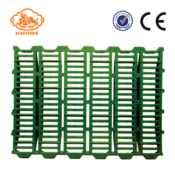
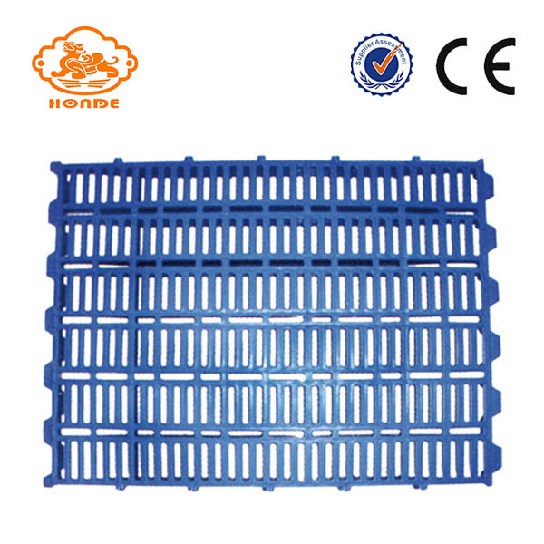
The pig Plastic slats are made of high-quality plastic, and are characterized by light weight, good thermal insulation, and can be used for the laying of pig crates.Plastic slats High Injection molding from virgin quality polypropylene copolymers creates durable long-lasting plastic flooring . easy cleaning , fast installation he turned-down edge prevents collection of dirt , which constitutes a bacterial risk. it also eliminates the risk of ear tags getting caught and possibly ripped off, causing ear damage.Our pig plastic slats are of guaranteed quality, durable and can last for a long time. If the buyer is dissatisfied with our samples, we can also make according to customer requirements, or according to the samples provided by customers. Color and size can be changed according to customer's needs.


|
1290
|
400*600mm
|
for sow
|
|
1291
|
400*600mm
|
for piglets
|
|
1292
|
500*600mm
|
for piglets
|
|
1295
|
600*600mm
|
for piglets
|
|
1296
|
700*600mm
|
for piglets
|
Pig Plastic Slat
Pig Plastic Slat,Plastic Slat Floor For Pig,Plastic Slatted Flooring,Pig Plastic Slat Floor,Plastic Floors For Pigs,Plastic Pig Floor
HuangHua FengYi Honde Metal Factory , http://www.farrowingcratesfromchina.com


